INITIATION TO BOOLEAN ALGEBRA Part 2 - Sequence Charts
Those familiar with ladder logic and PLC, often use their experience and intuition to build a set of ladder
diagrams that will satisfy certain logic requirements. The time it takes to arrive at a solution with this
trial and error method will depend on how much experience you have.
There are techniques that will lead to a solution systematically. The study of these techniques also gives
us some insight on what logic really is.
The Sequence Chart.
A sequence is a repeatable series of events.
A sequence can be represented in a chart that depicts the events chronologically, but without a specific unit of time.
There are three axioms associated with sequence charts:
(1) The starting state and the final state of the inputs and outputs are identical.
(2) Two inputs cannot change state simultaneously.
(3) For the same state of the inputs, the outputs must in the same state
We will use the 'memory' to illustrate how a sequence chart works:
 At time 0 both buttons are released and the coil is off
At time 1 the START button is pressed and the coil is energized
At time 2 the coil has completed it's mechanical action and MOTOR shows on
At time 3 the START button is released.
At time 4 the STOP button is pressed and the coil is de-energized
At time 5 the coil has completed it's mechanical action and MOTOR is off
At time 6 the STOP button is released.
At time 6 we are back in the exact same conditions as time 0 - and we can repeat the same sequence
over and over. This satisfies Axiom 1.
We have made sure that 2 inputs never change state at the same time, thus satisfying axiom 2.
One way to verify that Axiom 2 is satisfied is to allocate to each input
a value (a weight) and calculate the value of each column as the total of the weights.
Using succesive powers of 2, the total of the weights in each case
is unique for every combination of the weights. (e.g: the only way to obtain a total of 7, using powers of 2,
is 1+2+4). This is how the sequence chart looks with the weights assigned to the inputs and states.
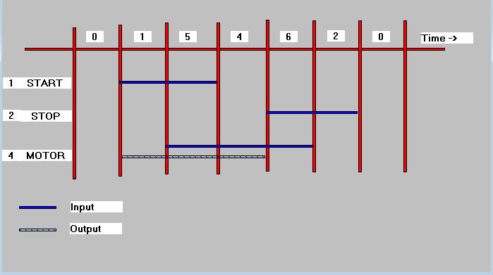 In this case, the only 2 columns that have the same value are the 1st and the last (0) and for both these
columns the output(s) is/are the same.
We may now proceed with building the boolean expression that represents MOTOR. It is the OR of all the columns
where MOTOR is true (on). That would be columns with the values 1, 5 and 4.
MOTOR = START & STOP' & MOTOR ' ! START & STOP' & MOTOR ! START' & STOP' & MOTOR
We could use the above expression as the solution for our logic. However, it is interesting to see how
the basic theorems was boolean algebra would allow us to simplify the rule.
[& is distributive] MOTOR= STOP' & (START & MOTOR' ! START & MOTOR ! START' & MOTOR)
In this case, the only 2 columns that have the same value are the 1st and the last (0) and for both these
columns the output(s) is/are the same.
We may now proceed with building the boolean expression that represents MOTOR. It is the OR of all the columns
where MOTOR is true (on). That would be columns with the values 1, 5 and 4.
MOTOR = START & STOP' & MOTOR ' ! START & STOP' & MOTOR ! START' & STOP' & MOTOR
We could use the above expression as the solution for our logic. However, it is interesting to see how
the basic theorems was boolean algebra would allow us to simplify the rule.
[& is distributive] MOTOR= STOP' & (START & MOTOR' ! START & MOTOR ! START' & MOTOR)
[a&b!a&b'=a] MOTOR = STOP' & (START ! START' & MOTOR)
[a!a'&b=a!b] MOTOR = STOP' & (START ! MOTOR)
That looks familiar !