RTES Communication - Drivers
Table of contents
Device drivers are software modules that handle the communication between RTES and other devices or systems such as I/O subsystems, instruments, scales, PLC's, HMI's DCS's and other computers running RTES.
Drivers are usually named after the device they are designed to talk to, or they are named after the protocol they use. Other drivers simply get their name from the function they perform.
For example, IOPLEX.EXE is the driver for an IOPLEXER network and DNP3.EXE is the driver that allows communication with other systems using that protocol.
Each device driver is associated with - or occupies - a PORT. There are 5 ports available, named PORT0 through PORT4. We load the device drivers in memory, as "terminate and stay resident programs", before we start RTES. As we load them, we assign them to a given PORT by naming the port number we want to use on the command line.
For example, the command line
MODRTU 2
loads the MODRTU.EXE driver and assigns it to PORT2.
When the port number is missing on the command line, it is assumed to be (defaults to) 1 or 0, depending on the driver (see details on the page for the individual driver).
When a driver is assigned to PORTn, it expects configuration file named PORTn.CNF to contain the information it will use for your specific application.
Configuration files are plain text files that describe how RTES will interface with the device. The onfiguration file contains parameters and I/O assignements.
Parameters [To Top]
Parameters contained in the configuration file define baud rate, COM port location, time-out duration, and relationship between the elements of the device and the RTES database (I/O assignment).
Inside the configuration file, we can define the following parameters. All the parameters are not applicable to all drivers. Some of them may not be relevant. You will find the details in the section that deals with the specific driver you are using. Typically, you define a parameter by typing a key letter, followed by the = sign, followed by the value you assign to that parameter. Here are the parameters used by most drivers and how you use them.
|
Parameter |
Key letter |
Description |
Default value |
|
Quantity of A type clusters |
A |
Type A clusters (see below) usually transfer analog data to a block of
RTES "A" registers. There are exceptions specific to the driver used. |
A=0 |
|
Baud Rate |
B |
Set baud rate Allowed values are 300, 600, 1200, 2400, 4800, 9600, 19200, 38400 |
B=19200 |
|
Enable flag option |
C |
You can enable/disable each communication cluster individually,
using a RTES as a 'switch'. This parameter dtermines the behaviour of that switch. |
C=0 |
|
Quantity of I type clusters |
I |
Type I clusters (see below) usually transfer binary data to a block of
RTES "I" registers. There are execeptions specific to the driver used. |
I=0 |
|
Quantity of G type clusters |
G |
Type G clusters (see below) usually transfer numeric data to a block of
RTES "R" registers. There are exceptions specific to the driver used. |
G=0 |
|
Line characteristics |
L |
Set parity, data bits and stop bits The value of this parameter is a mask obtained by adding the values for the individual characteristics. DATA BITS value 5 0 6 1 7 2 8 3 PARITY value NONE 0 ODD 8 EVEN 24 MARK 40 BLANK 56 STOP BIT(S) value 1 0 2 4 Example: L=26 (7 data bits, even parity, 1 stop bit)
|
Set to the values specified by the protocol and device in use. |
|
Modem control |
M |
Allow modem signals and dial - up modem. M=0 no modem. The Request-To-Send is maintained high continuously. M=1 leased line modem or multidrop line. The driver raises Request-To-Send and waits for Clear-To-Send before sending data. M>1 dial-up modem (click here for details) |
M=0 (no modem) |
|
Station number |
N |
Set station number This parameter is only used in some drivers that allow for a master/slave or peer-to-peer configuration |
N=1 |
|
Quantity of O type clusters |
O |
Type O clusters (see below) usually transfer binay data from a block of
RTES "O" registers. There are exceptions specific to the driver used. |
O=0 |
|
I/O Port |
P |
Set I/O Port Address (in decimal) |
When used in PORT1.CNF P=1016 (3F8 or COM1) |
|
When used in PORT2.CNF P=760 (2F8 or COM2) |
|||
|
When used in PORT3.CNF P=1000 (3E8 or COM3) |
|||
|
When used in PORT4.CNF P=744 (2E8 or COM4) |
|||
|
IRQ number |
Q |
Set IRQ number Note : Each driver that uses an interrupt must be assigned its own interrupt number that is not used by any other device in the computer. |
When used in PORT1.CNF Q=4 |
|
When used in PORT2.CNF Q=3 |
|||
|
When used in PORT3.CNF Q=4 |
|||
|
When used in PORT4.CNF Q=3 |
|||
|
Quantity of S type clusters |
S |
Type S clusters (see below) usually transfer numeric data from a block of
RTES "R" registers. There are exceptions specific to the driver used. |
S=0 |
|
Quantity of Y type clusters |
Y |
Type Y clusters (see below) usually transfer analog data from a block of
RTES "Y" registers. There are exceptions specific to the driver used. |
Y=0 |
|
Timeout |
T |
Defines the time in milliseconds that the driver will wait for a response (data and/or acknowledgement) before deciding that there is no response. The 'Alarm' register of the cluster is then set to 1. When data is received but does not constitute an answer - due to noise for instance - the driver discards the data received and waits for the timeout before going to the next request. |
T=512 |
I/O Assignements
[To Top]When exchanging data - binary or analog or text - between RTES and some other device you must specify where the data is coming from and where it ends up. We generally consider blocks of contiguous variables to 'copy' from one side to the other. The block is defined at both ends by a starting 'address' and a length. Such blocks of data are called "I/O clusters". The address part is defined differently depending on the device : it could be a position on a given I/O board, or the address in the memory in a PLC, or the data register in a scale with a specific id number. Within RTES, the starting address is the index of the first register used. The length is the quantity of consecutive registers in the cluster. Depending on the specifics of the variable(s) transferred and the capabilities of the communication link, the maximum quantity may vary from 1 to several hundreds.
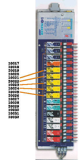
To illustrate this concept, consider a situation where we read the status of some digital inputs from a IOPLEXER board. The digital address of the IOPLEXER is 66. We want the status of the 5 inputs located at channels 4,5,6,7,8 to be indicated at the RTES binary inputs I0021 through I0025.
On the RTES side, the address of the first variable is 20. The 'I ' part is implied by the cluster type and quantity of clusters that will precede this cluster in the configuration file.
On the IOPLEXER side, the address of the first variable is 66,4
The length of the cluster is 5.
To make the cluster definition more complete, we specify the index of a RTES 'R' register that will be set to 1 by the driver whenever it does not get a response, or gets a bad response when requesting the data. Let's pick R0122 (index is 121). This will be the "alarm" register.
We also define another parameter "enable" that will dictate when the data will be transferred. Let's set this to 0 for now.
The configuration file will contain:
I=1               ;type and quantity of Clusters
20,5,66,4,121,0   ;cluster defined
Communication with serial devices over TCP/IP [To Top]
Devices drivers are available to support serial communication using most protocols via Ethernet, using 'microservers' (TCP/IP to serial adapters). The protocols currently supported are:
The configuration files for these drivers include a table that associates each device with a given IP address, although several devices may share the same IP address - as it is the case in a RS485 configuration.
This table is defined as follows:
P=number of devices
Example: OPTOMUX boards 2, 3 and 10 are attached to IP 111.111.111.006-007-008, respectively
P=3
This method eliminates the need for costly serial communication cables, allows the devices to be located farther away and allow several devices of different types to be served by the same LAN.
device1_id, 4byte_ip1
device2_id, 4byte_ip2
devicen_id, 4byte_ipn
2,111,111,111,006
3,111,111,111,007
10,111,111,111,008